In the field of Embedded Systems, integrating sensor technologies with autonomous functions is becoming crucial. By combining visual and spatial sensing, robotic platforms can perceive their surroundings more accurately — laying the groundwork for applications in industry, logistics, and security.
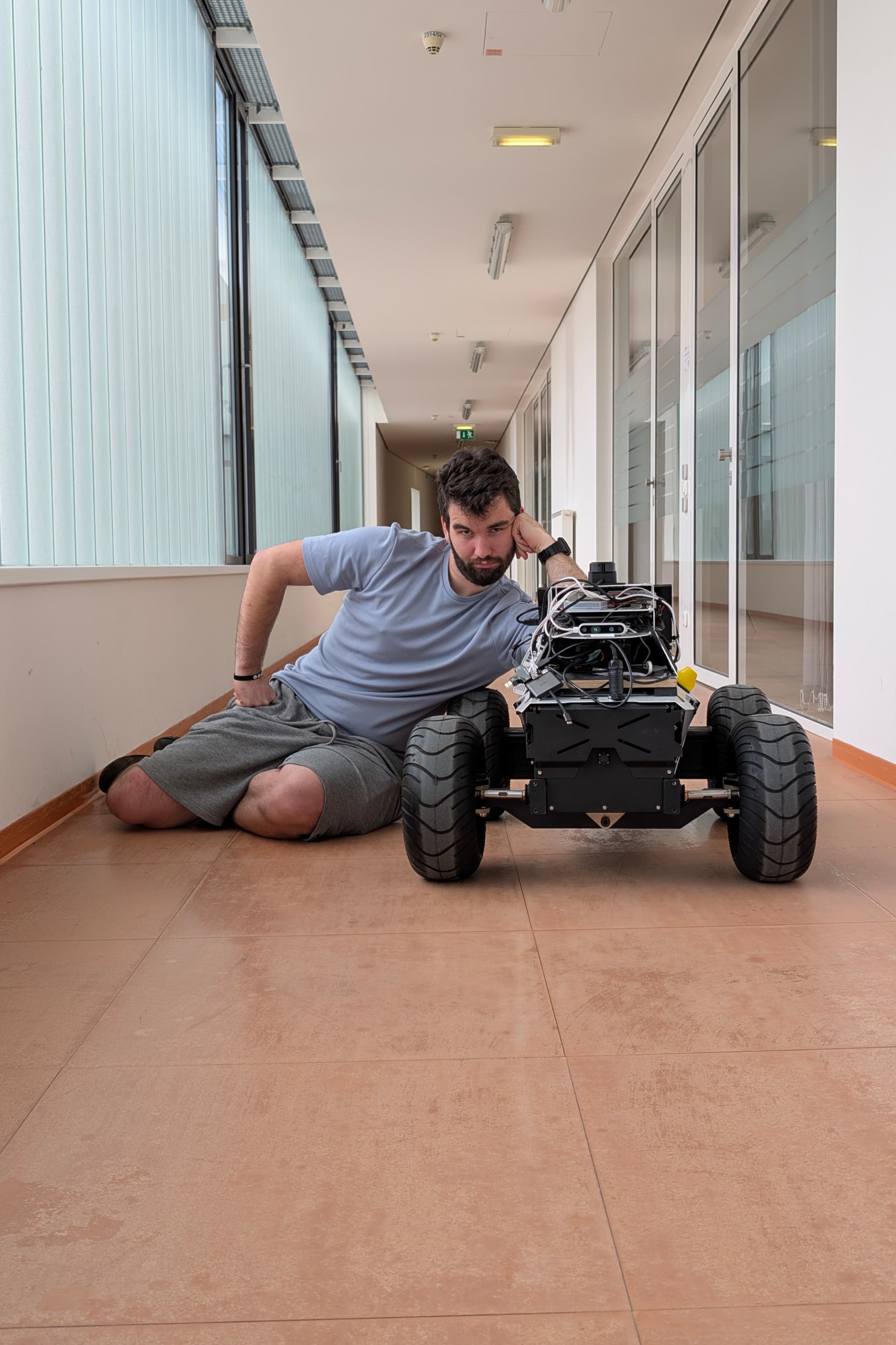
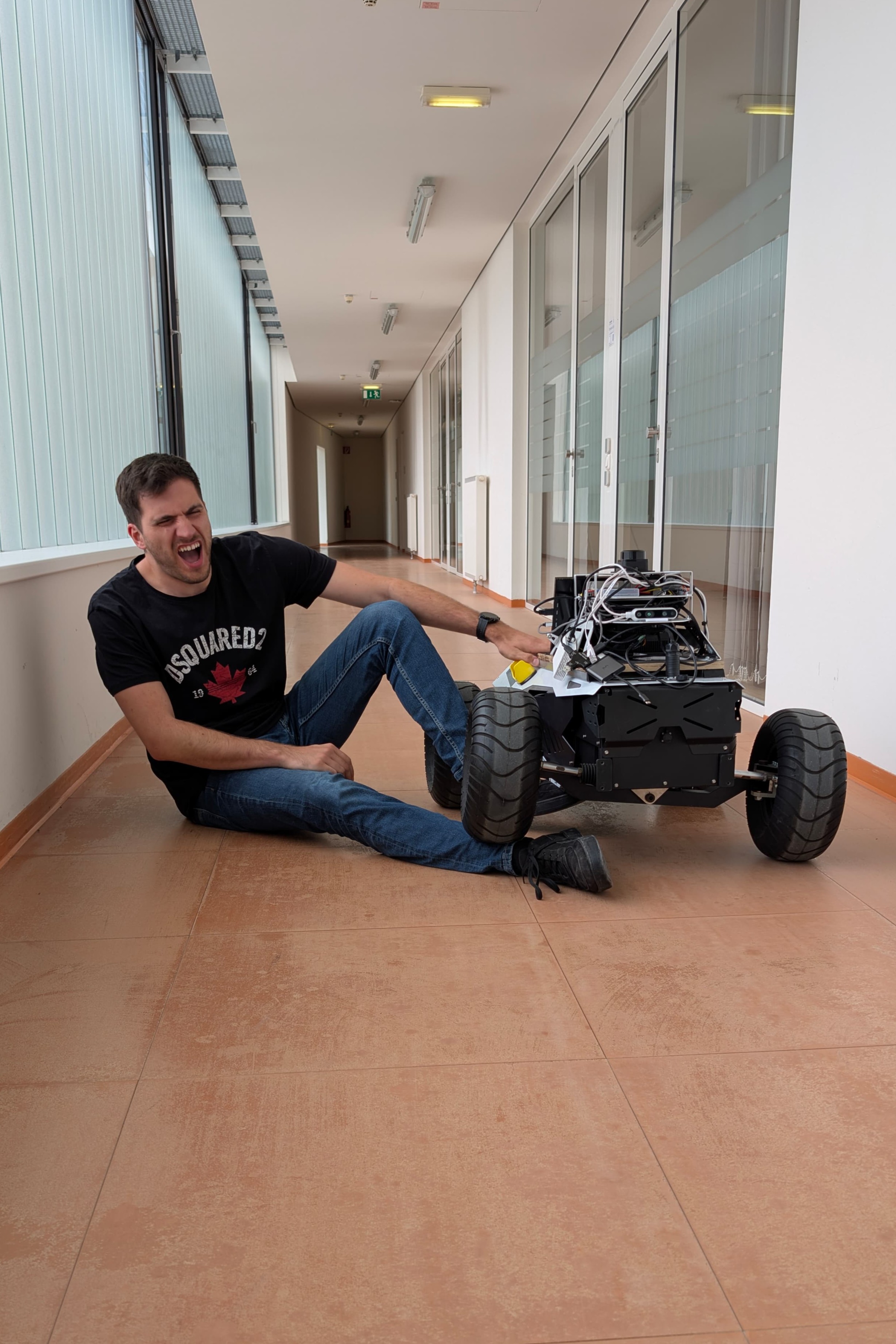
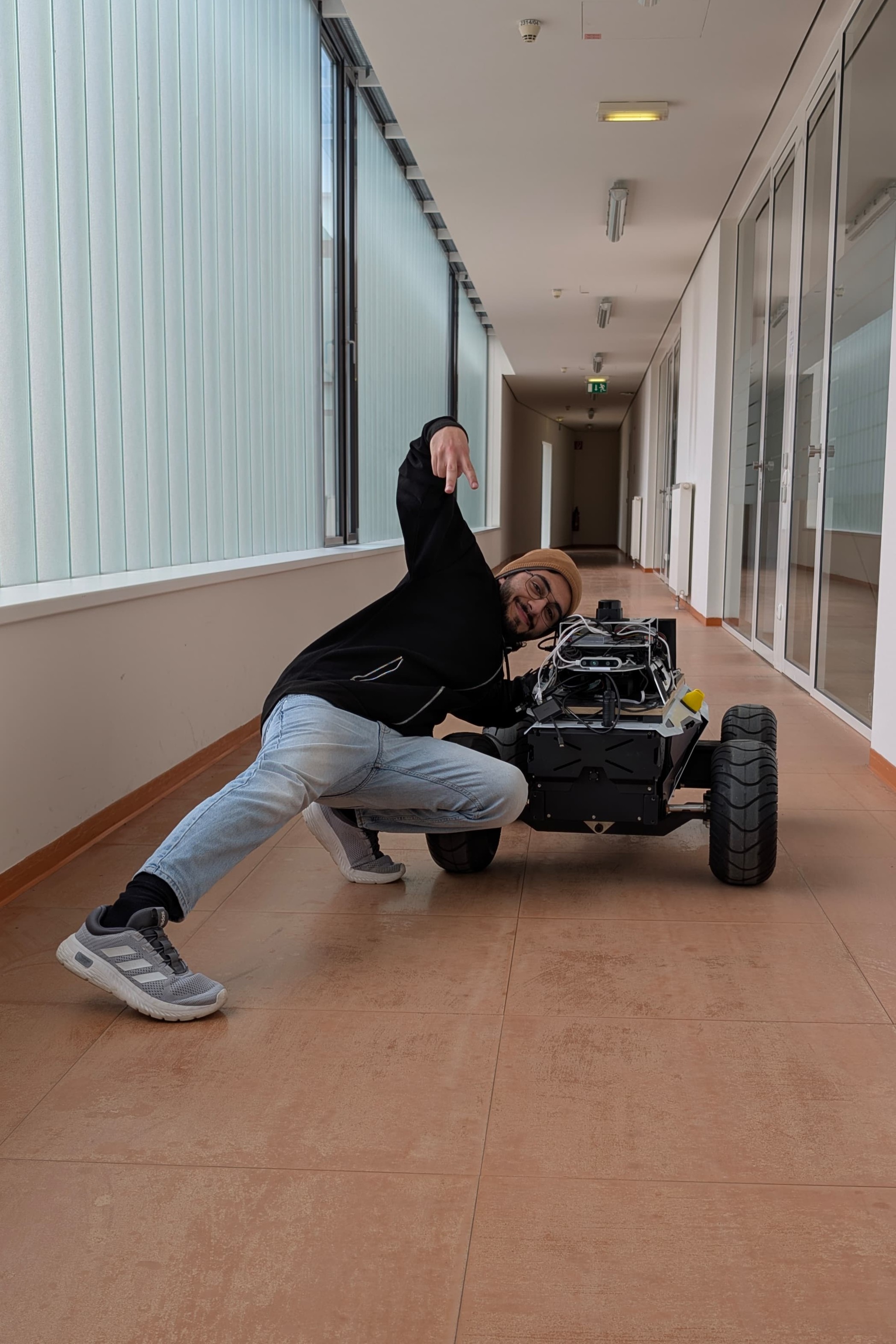
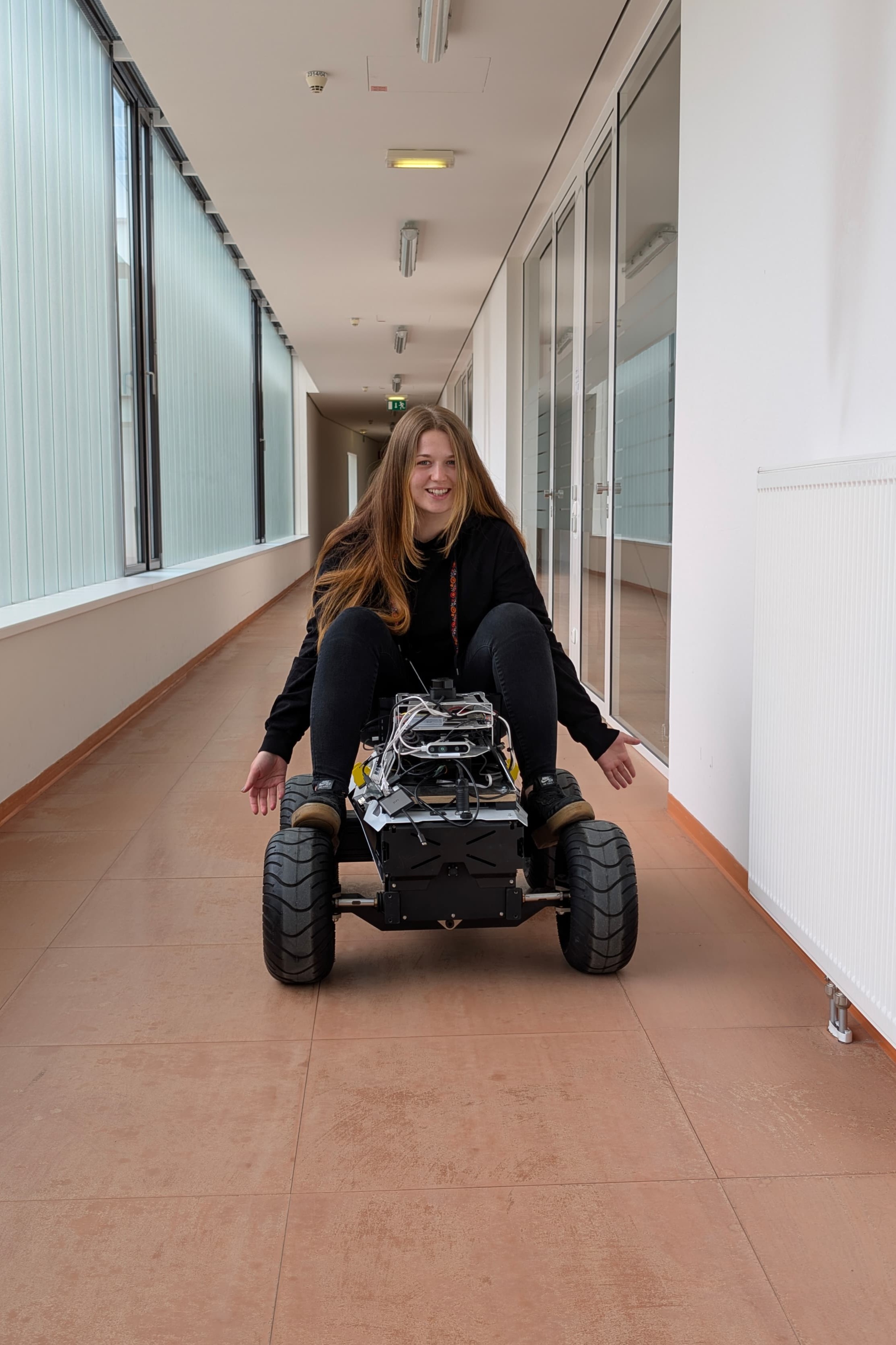
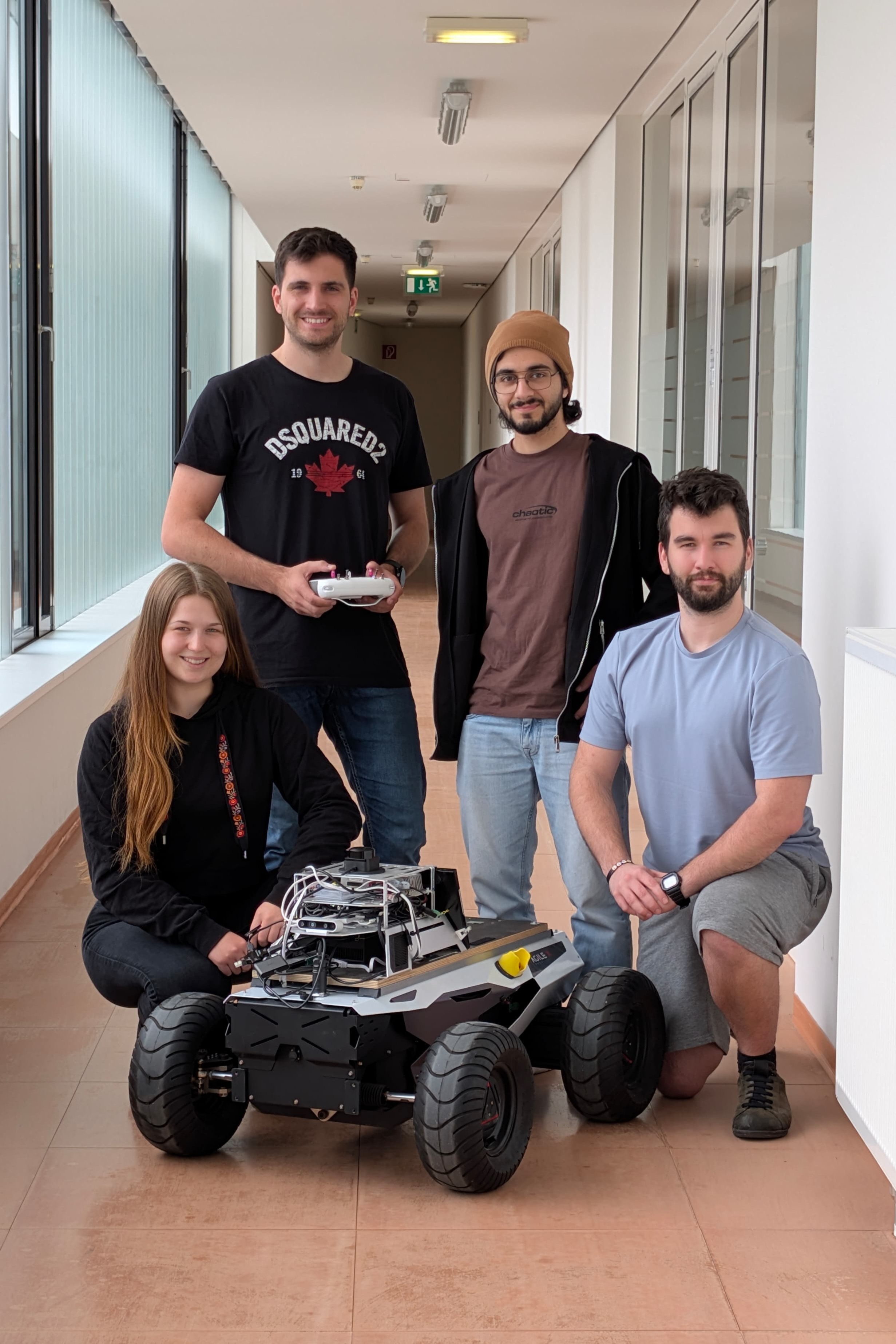
We're using a four-wheeled AgileX robot supplied by our industry partner, Magna. It already carries an Intel RealSense camera for color and depth data, and a previous student team completed the initial hardware and software setup.
This project focuses on equipping the robot with advanced navigation and AI to autonomously navigate through dynamic environments.
The AgileX Hunter 2.0 platform used for this project came equipped with an additional R&D rack, which houses an NVIDIA Jetson AGX Xavier for onboard computation. The Jetson runs Ubuntu 20.04 and has ROS2 Humble installed. It is used as a communication and orchestration framework for all robotic components.
ROS2 is used to interface with both the Intel RealSense camera and the vehicle's motor controller, for messaging across modular software nodes. Custom ROS2 packages were written in Python Code.
The motor controller communicates via CAN Bus, allowing the ROS2 stack send steering and throttle commands. The RealSense camera connects directly to the Jetson via USB-C for transmitting direct video footage to the system.
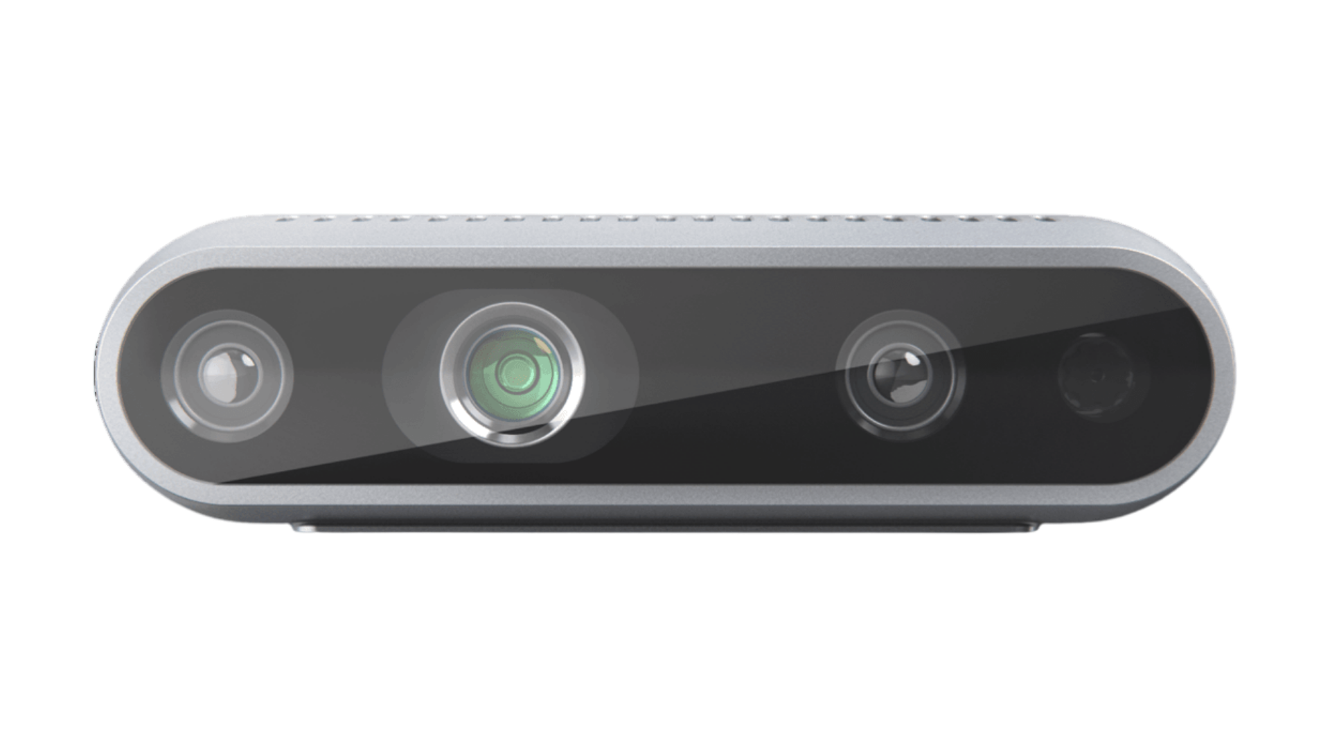
The Intel RealSense D435 is a compact USB-powered depth camera that captures up to 1280x720 depth images and full-HD (1920x1080) color video at up to 90 FPS, with a wide field of view and reliable performance from about 0.2m to over 3m.
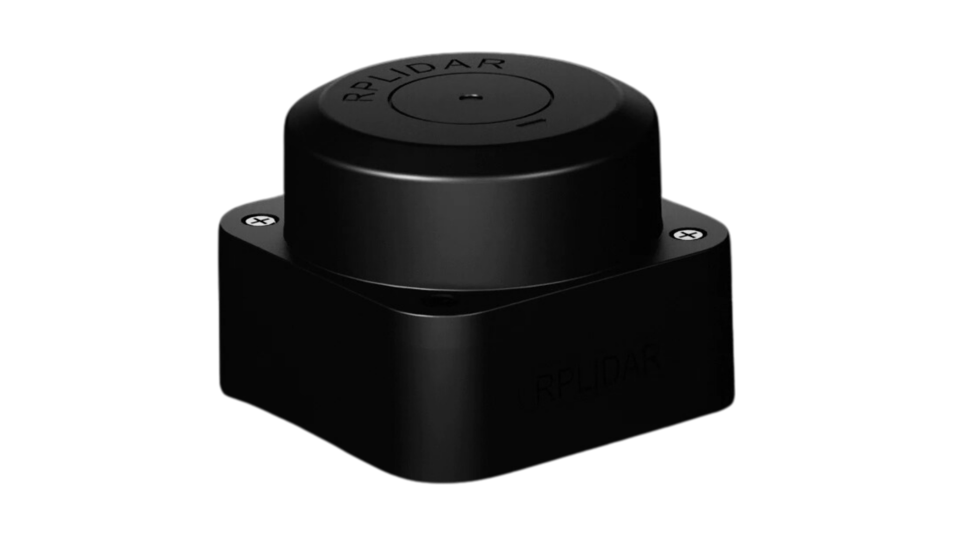
The SLAMTEC RPLIDAR C1 is a compact 360° laser scanner that takes up to 5000 distance measurements per second across a 12m radius — accurately mapping obstacles from just 5cm out to long range. Lightweight and easy to integrate, it uses a low-power Class 1 infrared laser and comes with ROS/ROS2 support for rapid setup on any robot.
A Gazebo-based simulation environment was set up to test the “Hunter 2” rover without having to rely on the physical robot. First, the AgileX rover was modeled in URDF/XACRO-Files with accurate physical parameters to ensure realistic vehicle dynamics.
A detailed 3D reconstruction of the third floor of the FH2 building was then designed and imported into Gazebo so that virtual tests mirror real-world conditions.
An Ackermann steering controller, tuned to the rover's kinematic and inertial characteristics, manages the virtual drive train. ROS2 Humble on Ubuntu 20.04 (ARM) running on an NVIDIA Jetson AGX Xavier handles bi-directional data exchange between Gazebo and the hardware stack, allowing sensor drivers and control nodes - ranging from the LiDAR interface to the Nav2 navigation node - to operate identically in simulation and on the physical robot.
RViz2 serves as the primary visualization tool, offering interactive displays of sensor data, SLAM outputs, and coordinate frames to monitor and debugging in real time.
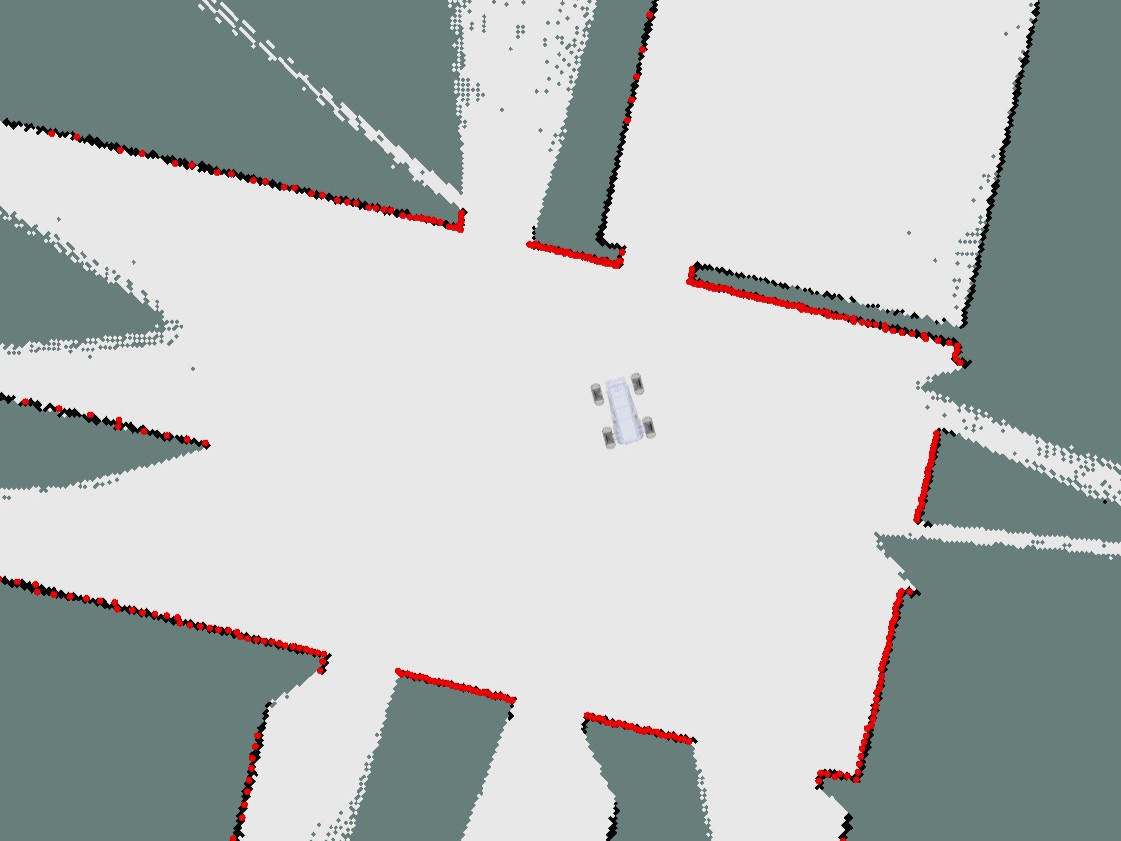
Mapping is based on the RPLIDAR C1, which was first commissioned and integrated into the ROS2 framework. Using the SLAM Toolbox package, real-time environment reconstruction is achieved: incoming 2D scans from the LiDAR are processed into a consistent occupancy grid.
In field trials on the third floor of the FH2 building, the rover traversed corridors and rooms while SLAM Toolbox automatically extracted wall contours, doorways, and obstacles to produce a complete map. This generated map serves as the foundation for both autonomous navigation and higher-level perception tasks by providing a reliable spatial reference for localization and path planning.
In order to adapt to ambiguous path-finding options, the robot utilizes YOLOv11-based arrow detection to interpret directional cues from its Intel® RealSense™ D435 depth camera data. This feature enables the robot to detect and follow arrow signs in real time, thereby providing the capability to dynamically adjust its route when prompted.
The system works by detecting the geometric shape and specific color of our designated magenta arrow. This particular color and design were chosen after experimenting with different arrow versions. Initially, we used a bright red arrow, but this resulted in numerous false positives, as the camera often misinterpreted red objects in the environment as arrows. By switching to a magenta-colored arrow, we significantly reduced misdetections due to its higher visual contrast in most typical surroundings.
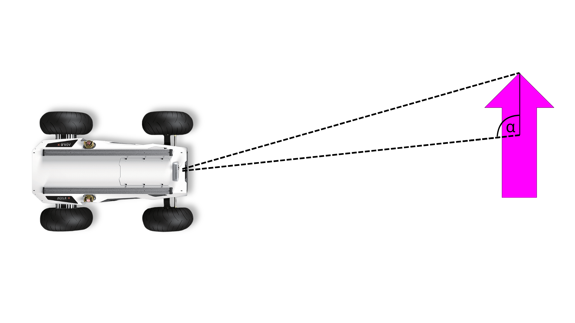
To measure the arrow's orientation, the algorithm identifies two distinct parts of the arrow and calculates the angle between the midpoints of these detections. This method allows reliable estimation of the pointing direction without relying on computationally expensive oriented bounding box (OBB) machine learning models.
The YOLOv11 model was trained with a dataset of 120 labeled images. We initially used Roboflow for annotation and labeling but later switched to Label Studio for better control and flexibility. With this dataset and our tailored approach, we achieved a lightweight and accurate arrow detection system optimized for real-time robotic navigation.
Integration into our ROS-based environment required the development of a dedicated ROS node, which executes the arrow detection and publishes its results to the ROS network. This node provides three key pieces of information: the orientation angle of the arrow, its distance from the robot, and its horizontal placement within the camera’s field of view. These values are then consumed by other ROS nodes to inform the robot's path-planning logic.
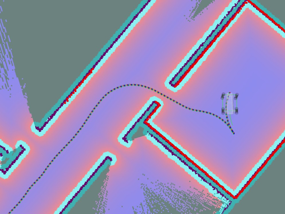
In order to manipulate the calculated path to follow the arrow, a keep-out zone is set on the rear end of the arrow. This leverages the concept of cost functions in the planning algorithm. Based on the angle between the arrow and the robot, the position for the keep-out zone is calculated.
For the detected arrow to actively influence path decisions, we implemented the following method: whenever an arrow is detected, a virtual "keep-out zone" is dynamically placed on the side opposite to the arrow's pointing direction. This keep-out zone is interpreted by the planner as a high-cost area to avoid. As a result, the robot is guided to select the only remaining viable option — the direction indicated by the arrow itself. This approach allows for a smooth and intuitive integration of visual cues into the robot’s autonomous navigation logic.
Project Lead
AI and object detection
Vice Project Lead
Mapping, Navigation and Simulation
Creative Vice Lead
AI and object detection
Creative Lead
Simulation, Navigation and Media